PRODUCTS
OUR
PRODUCTS
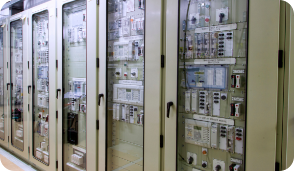
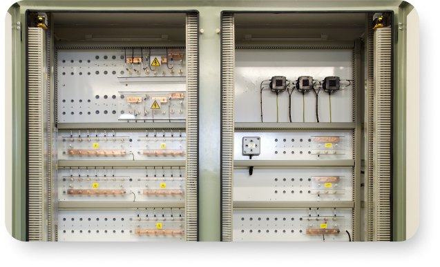
Protection & Control Panels
Protection and Control panels form the core of substation control for HV Protection & Control systems, housing modern relays, control equipment, and wiring in tailored configurations. These protection panels include freestanding 19-inch rack panels, rear-access cubicles, front-access swing-frame designs, and compact wall boxes for sites with limited space. Replacement front sheets can be provided as direct-fit upgrades, complete with inter-device wiring and flying leads. In addition, mimic control panels and cubicles are supplied to provide clear system visualisation and operational control across transmission, distribution, and generation assets. The panels support all major relay manufacturers and are built to suit any environmental or operational requirements. Each solution is engineered for easy integration with both new and existing sub-station control panels.
Features
- Freestanding 19" rack-type panels
- Rear-access and front-access swing-frame designs
- Replacement front sheets with full internal wiring and flying leads
- Uses relays from GE Vernova, Hitachi, SEL, Schneider, Siemens, etc.
- Wall-mounted boxes for compact substation layouts
- Panels built to suit specific environmental conditions
Key Highlights
- Suitable for electricity utilities, private connections, industrial sites, and renewables
- Custom-built to match existing infrastructure
- Supports both new installations and legacy system upgrades
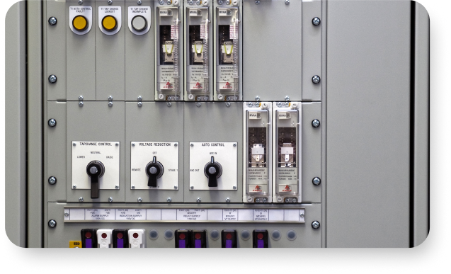
Automatic Voltage Controllers & Tap-Change Control
Automatic Voltage Controllers manage transformer tap-changing schemes for single or multiple transformers in a single cabinet or enclosure. They maintain proper voltage levels and ensure stable system performance, supporting effective power system design. Built around market-leading AVC technology, these systems help operators maintain consistency across varying load conditions. They can be integrated into new builds or used to upgrade older tap-change systems.
Features
- Tap-change control for single or multiple transformers
- Market-leading AVC solutions in a single cabinet or enclosure
- Fully engineered for transformer voltage regulation
- Suitable for diverse applications across power networks
Key Highlights
- Provides transformer voltage control schemes
- Delivered as a complete integrated solution
- Supports both single-transformer and multi-transformer arrangements
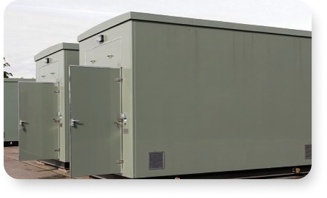
Modular Relay Rooms & Control Rooms
Modular relay rooms provide fully integrated, factory-commissioned protection and control environments delivered directly to site. These modular buildings contain interconnected sub-systems including protection schemes, SCADA RTUs, battery systems, HVAC, and AC supplies. They allow simple plug-and-play connection to a single marshalling kiosk. Modular construction supports fast deployment, especially near project completion dates.
Features
- Custom protection and local control scheme integration
- Fully integrated SCADA RTU
- Built-in battery and charger systems
- Heating, lighting, AC supply, and optional air-conditioning
- Central marshalling box with gland plate
- Delivered factory-commissioned
Key Highlights
- Self-contained modular buildings
- Quick on-site integration with plug-and-play connectivity
- Ideal for substation and wind-farm installations
Substation Marshalling Kiosks
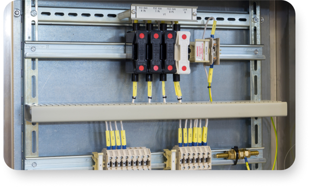
Marshalling kiosks consolidate control, protection, and instrumentation wiring within substations. These marshalling kiosks are designed in stainless steel for outdoor use or mild steel for indoor sites, and each kiosk is custom-built for the required equipment and future expansion. They provide organised and accessible termination points for field wiring associated with transformers, switchgear, and SCADA systems.
Features
- Indoor or outdoor custom-built kiosks
- Stainless steel (outdoor) or mild steel (indoor) construction
- Front or front-and-rear access options
- Cable terminals and expansion terminal rails
- Fuse and test-link arrays
- Cable management facilities and gland plates
- MCB arrays, switches, isolation points,insulation barriers, auxiliary sockets
Key Highlights
- Hundreds installed throughout the UK
- Built to customer-specific layouts and expansion needs
- Supports all substation plant connection requirements
CT & VT Marshalling Boxes
CT/VT marshalling boxes provide termination points for instrument transformer signals and route them safely to protection and control panels. Constructed from stainless steel with front access, each enclosure is designed for the specific CT/VT application.
Features
- Outdoor stainless-steel construction
- Custom-designed per CT/VT application Front-access design
- Terminal rails and expansion terminals
- Fuse and link arrays
- MCB arrays
Key Highlights
- Hundreds installed throughout the UK
- Designed specifically for CT/VT signal handling
- Built for reliable outdoor performance
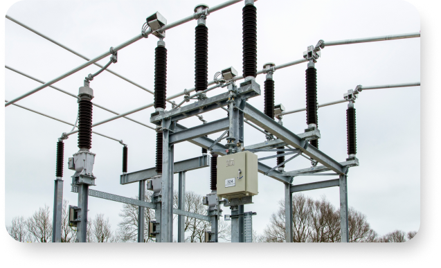
132 kV Disconnectors
These ENA-assessed 132kV disconnector switches use a double-break, centre-rotate design with a unique “turn and twist” movement that provides strong contact pressure, fault withstand, and self-cleaning action. They can be manually operated or motor-driven, supplied with or without supporting structures, and fitted with earth switches on one or both sides. The three phases are mechanically coupled for simultaneous operation.
Features
- Fully ENA-assessed 132 kV disconnector
- Double-break, centre-rotate design
- Manual or motor-driven operation
- Mechanical interlocks available
- Optional supporting structures
- Unique turn-and-twist contact movement
- Three-phase mechanically coupled operation
- Earth switches on one, both, or neither side
- Optional line discharging and bus-transfer contacts
Key Highlights
- Fully rated at 145 kV, 2000 A
- Hundreds of installations worldwide including UK and Ireland
- Fault-withstand capability with low operating torque
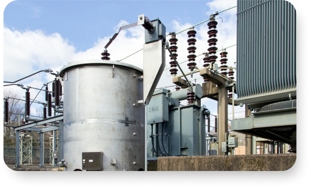
Liquid Neutral Earthing Resistors
Liquid Neutral Earthing Resistors limit fault currents using an electrolyte mixture inside a robust tank. Used for 11 kV and 33 kV applications, they remain vital for like-for-like replacement of older liquid resistor tanks. The electrolyte mixture is adjusted at commissioning to achieve the calibrated resistance level, supporting up to 30 seconds of rated current flow.
Features
- Electrolyte solution in a robust tank
- Inner electrode insulated from outer tank
- Resistance tuned by adding electrolyte during commissioning
- High short-duration current capability
- Long-lasting and durable construction
- Supports replacement of legacy liquid tanks
Key Highlights
- Almost 60 years of UK use
- Rated for up to 30 seconds of current flow
- Niche legacy product for 11 kV and 33 kV applications
SERVICES
OUR
SERVICES
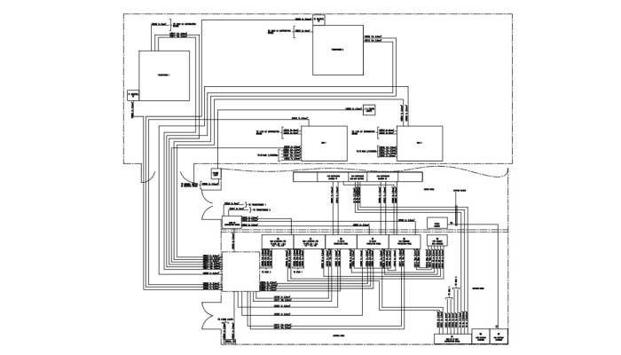

Interface Engineering
Interface Engineering defines how all substation subsystems interconnect through clear diagrams, core sheets, and termination schedules. It ensures correct cable types, core counts, lengths, and gland requirements. This structured documentation allows installation and commissioning teams to assemble complex systems with ease, avoiding errors and delays.
Benefits
- Reduced installation errors
- Faster commissioning
- Clear cable and termination mapping
- Accurate core usage and sizing
- Smooth integration of all subsystem elements
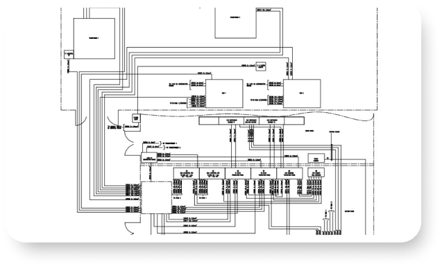

Protection & Control Design
Protection & Control design ensures power systems operate safely under normal and fault conditions. The process includes controlled design stages, checks, documentation, version control, and scheme testing. Designs account for system configuration, operating parameters, mechanical and electrical limits, and phased replacement strategies.
Benefits
- High-integrity design with controlled workflows
- Full documentation including wiring lists, diagrams, and BoMs
- Accurate terminal assignments and device representation
- Version control and traceability
- Compatible outputs in DWG, DXF, DWF, and PDF formats
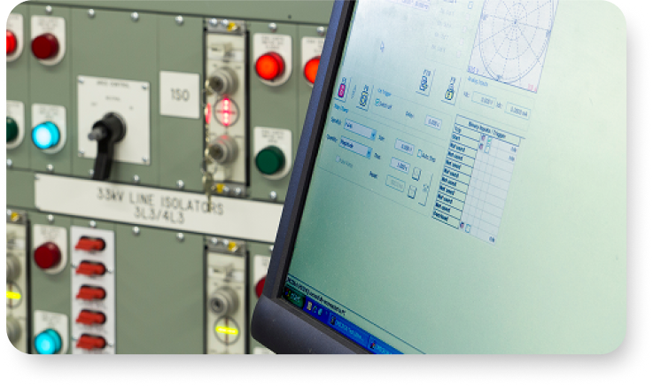
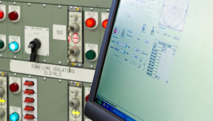
Protection Scheme Testing & Systems
Protection scheme testing validates design intent, relay settings, logic, wiring, and device interactions before equipment goes to site. FAT Levels 1–3 ensure mechanical checks, electrical tests, software validation, and full powered scheme testing. This reduces commissioning time and prevents design faults from appearing late in the project.
Benefits
- Earlier identification of design or logic issues
- Fewer commissioning delays
- Plug-and-play performance on site
- Fully validated protection logic and wiring
- Reduced troubleshooting and project costs